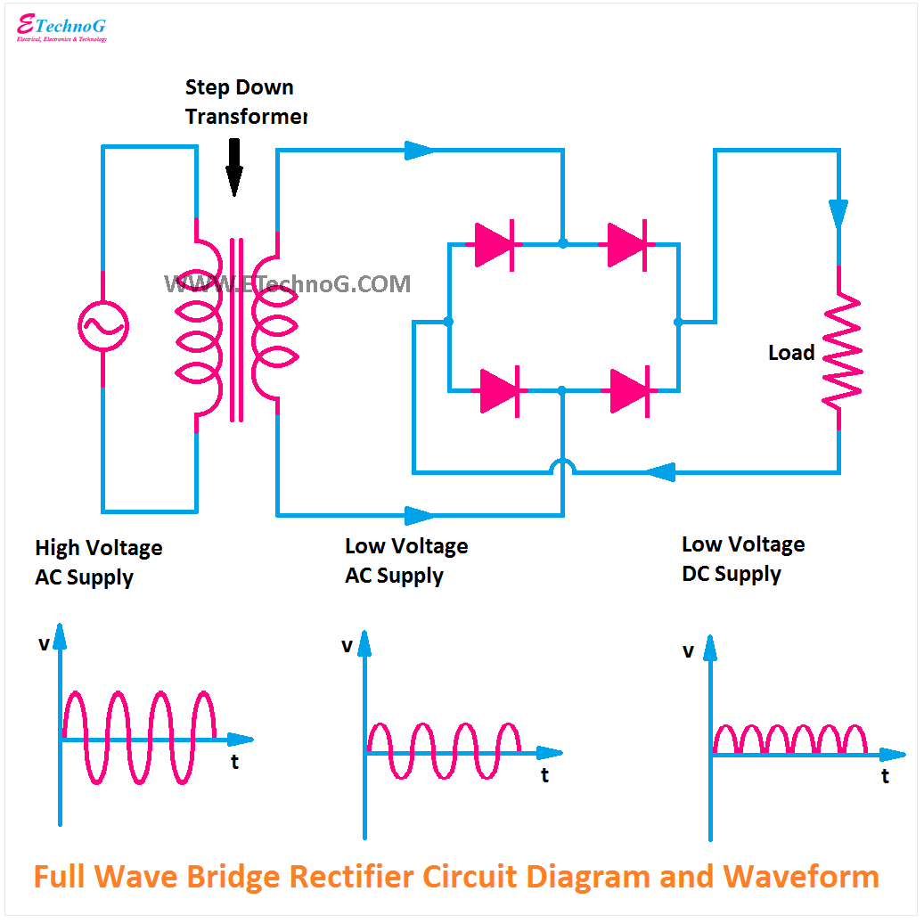
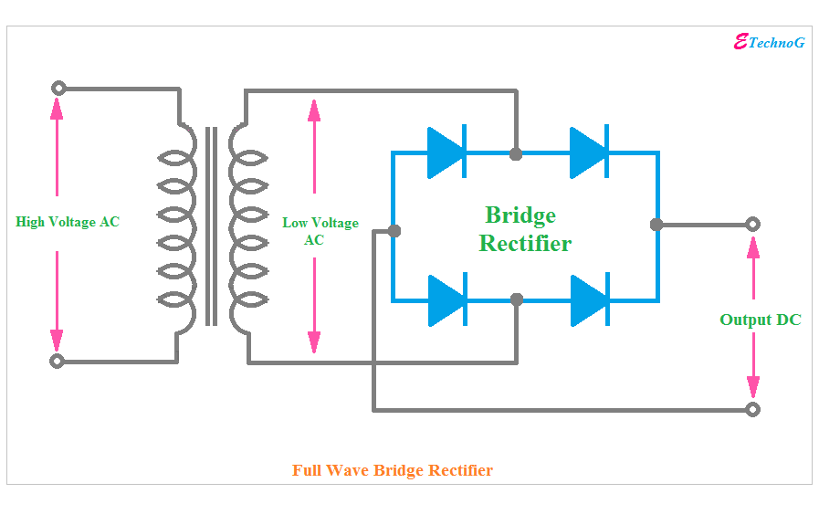
Full Wave Bridge Rectifier Circuit
Rectifier regulator regulators engineering regulated output engineeringtutorial Rectifier circuit diagram wave output waveform input Schematic of a full wave bridge rectifier
Full Wave Bridge Rectifier – Circuit Diagram and Working Principle
Rectifier circuit bridge diagram wave working details Full wave bridge rectifier circuit Rectifier includes electronicshub voltage
Rectifier bridge wave supply ac voltage dc circuit digital using parts down converts pulsating micro into part
Full wave bridge rectifier circuitRectifier capacitor resistor problem transcription solved Rectifier diode circuitsFull wave bridge rectifier circuit.
Rectifier bridge wave circuit diagram diode voltage operation peak fig its shown below inverse value when negativeRectifier bridge circuit wave diagram regulator ic Rectifier waveform diodes negative signal inductor biasedFull wave bridge rectifier circuit.

Rectifier wave schematic circuit converting basics
Rectifier multisim simulation diodesRectifier waveform capacitor signal resistor circuitglobe Different rectifier circuits and their workingExplain full wave bridge rectifier with diagram.
Rectifier waveformRectifier bridge wave circuit diagram capacitor filter prototypes application Full wave bridge rectifier supplyFull wave bridge rectifier.

[solved] only problem 2! repeat problem 1 for the full-wave bridge
Rectifier bridge circuitsThis post includes full wave bridge rectifier circuit diagram, working Full wave bridge rectifierFull wave bridge rectifier.
Full wave bridge rectifierRectifier circuit diagram Rectifier principleFull wave bridge rectifier – circuit diagram and working principle.

Full wave bridge rectifier circuit [multisim simulation]
.
.


Full Wave Bridge Rectifier Circuit

Explain Full Wave Bridge Rectifier With Diagram - PCB Designs

Full Wave Bridge Rectifier - its Operation, Advantages & Disadvantages
[Solved] Only problem 2! Repeat Problem 1 for the full-wave bridge

Full Wave Bridge Rectifier - PCB Designs

Different Rectifier Circuits and their Working - Electroinvention

Full Wave Bridge Rectifier Circuit - PCB Designs

Full Wave Bridge Rectifier Supply | Micro Digital
